LNG Cargo Containment Systems Explained
A practical guide to LNG carrier cargo containment: membrane and independent tank concepts, primary and secondary barriers, insulation, sloshing and design trade-offs.
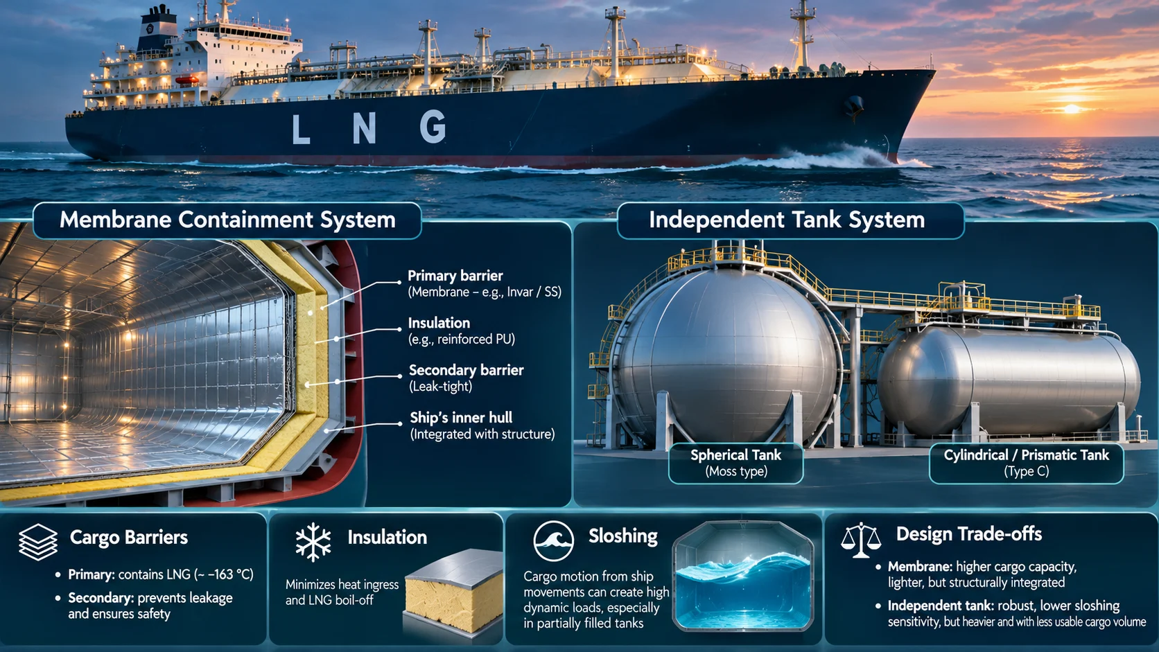
The containment system is the ship’s defining technology
An LNG carrier must keep its cargo at approximately atmospheric pressure and cryogenic temperature while exposed to a changing marine environment. The cargo containment system (CCS) is the engineered arrangement that performs this task. It includes the cargo tank or membrane, insulation, barriers, supporting structure, spaces between barriers and associated monitoring arrangements. It is not simply a tank: it is a safety-critical system integrated with the ship’s hull and cargo machinery.
Two broad design families
LNG containment systems are commonly grouped into membrane systems and independent, self-supporting tanks. In a membrane arrangement, a thin primary barrier is supported by insulation and the surrounding ship structure; a secondary barrier is provided to protect against leakage from the primary barrier. In an independent tank arrangement, the cargo tank is structurally self-supporting and is installed within the ship. Moss spherical tanks and prismatic independent tanks are examples of the latter family.
Membrane systems
Modern membrane carriers commonly use designs such as GTT’s Mark III and NO96 families. Their geometry makes efficient use of the ship’s hull volume and allows large cargo capacities. The membrane itself is thin, so the insulation and supporting arrangement are essential to managing thermal contraction, static liquid loads and dynamic loads. Different membrane technologies use different materials and construction details; they should not be treated as interchangeable.
Independent tanks
Moss-type tanks are spherical, self-supporting tanks that are structurally independent of the hull. Their geometry provides a robust tank form and a visible portion of the tank may extend above the deck. The trade-off is that the spherical shape can use the available hull volume less efficiently than a membrane arrangement. Other independent tank concepts, including prismatic designs, have their own structural and operational characteristics. Selection depends on vessel size, route, shipyard capability, owner requirements and the applicable design approval.
Primary and secondary barriers
The primary barrier is in direct contact with LNG. The secondary barrier is intended to provide protection if the primary barrier leaks, within the design and regulatory requirements applicable to the system. Insulation reduces heat transfer and supports the membrane or tank arrangement. Inter-barrier spaces may be monitored and maintained under specified conditions. Barrier integrity, insulation condition and monitoring trends are central to maintaining containment performance over the vessel’s life.
Thermal performance and boil-off
Heat inevitably enters the cargo system, generating BOG. The insulation design and construction quality influence the rate of heat ingress, but the actual boil-off rate is also affected by cargo and voyage conditions. Published design BOR values should always be read with their assumptions, vessel size and tank configuration. Comparing two containment systems solely by a single BOR percentage can be misleading if the reference conditions differ.
Sloshing and partial filling
Liquid motion inside a tank can create impact and dynamic loads on the containment system. These loads are commonly described as sloshing. Their significance depends on tank geometry, filling level, vessel motion and sea state. Membrane systems can have specific restrictions or approved operating envelopes for partial filling. The applicable loading limits are vessel- and design-specific and must be taken from approved documentation, not from generic rules of thumb.
Inspection, monitoring and lifecycle management
A containment system requires disciplined inspection and trend monitoring. Relevant information may include insulation-space conditions, gas detection, temperature distribution, pressure trends, structural inspections and records of abnormal events. Access to some components is limited, which makes preventive maintenance and reliable instrumentation particularly important. Any suspected damage, leakage or abnormal trend must be assessed under the vessel’s safety-management procedures and the designer’s guidance.
Conclusion
The best containment system is not determined by one feature alone. Cargo capacity, thermal performance, structural behaviour, sloshing limits, construction quality, maintainability, shipyard experience and lifecycle cost all matter. Understanding the underlying design helps operators interpret limitations correctly and manage the cargo system within its approved envelope.
Technical references
Related guides
LNG Carrier Technology: Containment Systems, Propulsion and Boil-Off Gas
Membrane and independent tank designs, steam, dual-fuel diesel-electric and two-stroke gas engines, and the options for handling boil-off gas — explained for technical decision-makers.