LNG Carrier Technology: Containment Systems, Propulsion and Boil-Off Gas
An engineering overview of how LNG carriers contain cryogenic cargo, how they are propelled and how boil-off gas is managed.
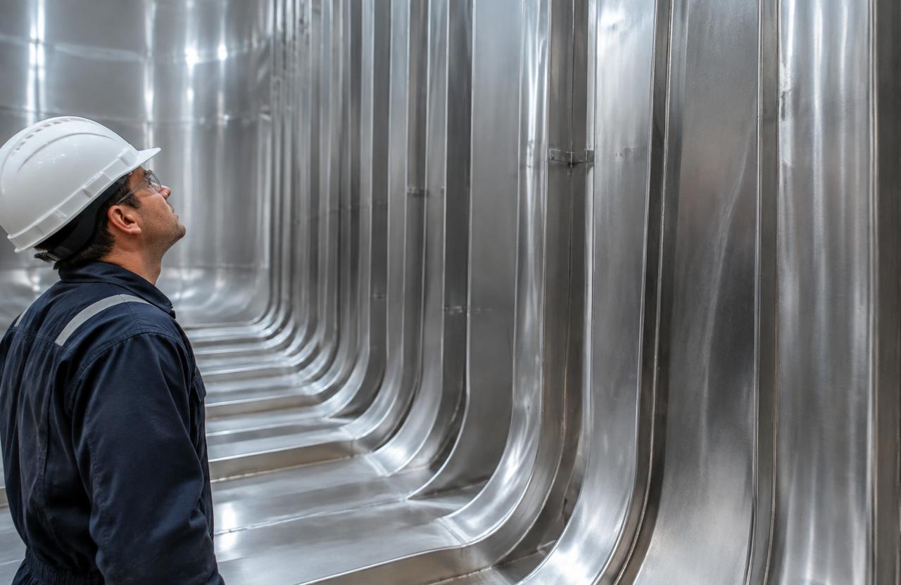
Three technical systems define an LNG carrier: the cargo containment system that holds LNG at approximately −162 °C, the propulsion plant, and the arrangements for handling boil-off gas (BOG). These systems are tightly linked — the amount of BOG a containment system generates and the ability of the propulsion plant to consume it have historically shaped vessel design. This guide explains each system and the trade-offs between design choices.
Design and construction requirements for these systems are set by the IMO IGC Code and the rules of classification societies. Specific proprietary designs are licensed by technology owners; where we describe typical characteristics, they are general and not a substitute for the designer’s or class society’s documentation.
Cargo containment systems
The IGC Code classifies cargo containment into membrane tanks and independent tanks, the latter subdivided into Type A, Type B and Type C. The classification determines the degree of secondary barrier required — that is, how much backup containment must be provided if the primary barrier leaks.
Membrane systems
In a membrane system, the cargo is held by a thin primary metallic barrier, supported through layers of insulation by the ship’s inner hull. The membrane itself carries little structural load; it must accommodate thermal contraction, which is achieved either through corrugations in stainless steel or through the very low thermal expansion of Invar, a nickel–iron alloy. A secondary barrier is incorporated within the insulation.
Membrane designs make efficient use of the hull volume and dominate the large-carrier orderbook in recent decades. Their operational considerations include sloshing loads in partially filled tanks, which is why filling limits are specified for certain operations, and the need for careful monitoring of insulation space atmospheres.
Independent Type B tanks
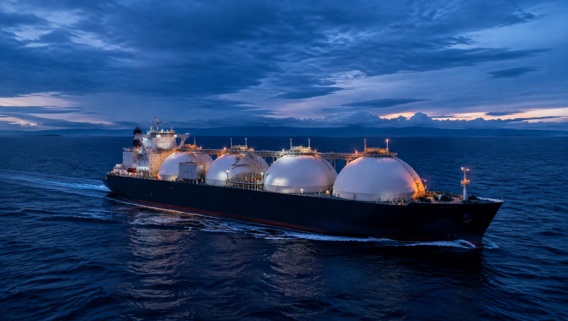
Type B tanks are designed using detailed stress and fatigue analysis, which allows a partial secondary barrier. The best-known example is the spherical tank design, recognisable by its domes protruding above the deck. Prismatic Type B designs also exist. Spherical tanks are robust against sloshing, but they use the hull volume less efficiently and increase windage.
Independent Type A and Type C tanks
Type A tanks are self-supporting prismatic tanks requiring a full secondary barrier. Type C tanks are pressure vessels — usually cylindrical or bilobe — designed to conventional pressure-vessel criteria, so no secondary barrier is required. Type C tanks are typical of small-scale carriers, bunker vessels and the fuel tanks of LNG-fuelled ships, because they can hold LNG for extended periods while pressure rises without venting.
Insulation and boil-off rate
No insulation is perfect. Heat ingress causes a fraction of the cargo to evaporate continuously, usually expressed as a boil-off rate (BOR) in percent of cargo volume per day. BOR depends on the containment design, the insulation thickness and material, the cargo composition and ambient conditions. Successive generations of containment systems have reduced design BOR substantially; actual performance is a matter of contract warranty and measured data for each vessel rather than generic figures.
In our interpretation, the commercial importance of BOR has changed as propulsion technology changed. When steam turbines burned BOG as their main fuel, a certain boil-off was useful. With more efficient engines that need less fuel than a vessel naturally boils off at slow speeds, surplus BOG has to be reliquefied or burned, so lower BOR became more valuable.
Propulsion systems
LNG carriers have used several propulsion concepts. Each is defined by how it uses BOG and how efficiently it converts fuel into propulsion.
Steam turbines
For decades, steam turbine propulsion was standard. Boilers can burn BOG, heavy fuel oil or both, which made them a simple and reliable way to consume boil-off. Their thermal efficiency is significantly lower than that of modern diesel engines, which means higher fuel consumption and emissions per tonne-mile. Older steam-turbine vessels therefore face strong commercial and regulatory pressure, and their future — continued trading, conversion to floating storage, or recycling — is an active question for owners.
Dual-fuel diesel-electric (DFDE/TFDE)
Dual-fuel four-stroke medium-speed engines driving generators, with electric motors turning the propeller, improved efficiency relative to steam and allowed engines to run on gas or liquid fuel. The electric configuration also provides flexibility for supplying cargo-handling and hotel loads.
Two-stroke dual-fuel engines
Slow-speed two-stroke dual-fuel engines, directly coupled to the propeller, have become common on newer large carriers. Two principal concepts exist: high-pressure gas injection, in which gas is injected at high pressure near top dead centre in a diesel cycle, and low-pressure designs operating on the Otto principle with gas admitted at lower pressure. The trade-offs involve gas supply system complexity and energy use, nitrogen oxide formation, and methane slip characteristics. Engine designers publish detailed technical data for each concept.
Boil-off gas management
Every LNG carrier must be able to control cargo tank pressure under all operating conditions. The main tools are:
Fuel consumption. BOG is compressed or conditioned and supplied to engines or boilers. This is the preferred use when propulsion demand is sufficient.
Reliquefaction. A reliquefaction plant condenses surplus BOG and returns it to the tanks. Systems range from partial reliquefaction using the cold energy of LNG to full plants based on nitrogen or mixed-refrigerant cycles. They add capital cost, power demand and maintenance, but preserve cargo.
Gas combustion unit (GCU). A GCU safely burns surplus gas without recovering energy. It is the safety backstop when gas cannot be used or reliquefied.
Pressure accumulation. Pressurised Type C tanks can allow pressure to rise within design limits, deferring the need to process BOG. Large membrane tanks have only limited pressure margin.
The IGC Code requires that the cargo tank pressure and temperature be maintained within design limits, and that venting of cargo to atmosphere is not used for pressure control in normal operation except in specified circumstances. Operators should consult the current text of the Code and class rules for the precise requirements.
Cargo-handling equipment
Other key systems include submerged electric cargo pumps installed in each tank, spray pumps for cool-down, high-duty and low-duty compressors, vaporisers and heaters, nitrogen generators, gas detection systems and the custody transfer measurement system used to determine the quantity of cargo loaded and discharged. Each is subject to class survey and to the operator’s planned maintenance system.
Frequently asked questions
Is a membrane or spherical tank design better?
Neither is universally better. Membrane designs use hull space more efficiently; spherical Type B tanks are inherently resistant to sloshing and have a long service record. The choice depends on trade, terminal compatibility, yard capability and owner preference.
What is methane slip?
Methane slip is unburned methane that passes through an engine into the exhaust. Because methane is a potent greenhouse gas, slip reduces the climate benefit of LNG as a fuel. The extent of slip differs between engine concepts and operating loads, and both engine designers and regulators are working on measurement and reduction.
Why do newer carriers install reliquefaction plants?
Efficient engines often need less fuel than the cargo naturally boils off, particularly at low speeds. Reliquefaction lets owners preserve that surplus as cargo instead of burning it in a GCU.
Related articles
Membrane containment systems, explained
Illustrative primer on membrane and independent tank designs. Demonstration content only.
Boil-off gas management: the operational basics
Illustrative primer on reliquefaction, fuel use and gas combustion units. Demonstration content only.
A guide to dual-fuel engine concepts for LNG carriers
Illustrative comparison of low- and high-pressure gas injection concepts. Demonstration content only.